
Introduction
An RJ45 wiring diagram is a simple visual guide that shows how the eight wires inside an Ethernet cable connect to the pins of an RJ45 connector. It uses numbered pins and color-coded wires to help you place each wire in the correct order before crimping or punching it down.
Correct wiring matters because even a small mistake can slow your network, cause connection drops, or stop devices from communicating at all. Ethernet cables depend on precise wiring to keep signals clean and stable, especially at higher speeds.
People often look for an RJ45 wiring diagram when setting up a home internet network, installing office cabling, fixing a damaged cable, or building custom patch leads for routers, switches, or wall outlets. Whether you are running cables through walls or simply making a short patch cable, understanding the diagram helps ensure everything works reliably from the start.
What an RJ45 Wiring Diagram Shows
An RJ45 wiring diagram acts like a roadmap for connecting Ethernet wires correctly. It shows the exact position of each colored wire, the numbered pins inside the connector, and the correct orientation of the plug while you work.
The diagram also explains how the eight wires are grouped into pairs. These pairs are twisted together inside the cable to reduce interference and keep data signals clear. When the wires are placed in the wrong order or the twist is removed too far, network performance can suffer.
Using a diagram helps prevent common wiring mistakes such as reversed connectors or mixed-up wire pairs. Instead of guessing, you follow a visual pattern that ensures both ends of the cable match the same standard. This small step can save time, prevent troubleshooting later, and keep your connection stable.
RJ45 Pinout Basics and Wire Pair Functions
Every RJ45 connector has eight pins, numbered from one to eight. These pins connect to four twisted wire pairs inside the cable. Each pair carries electrical signals that allow data to travel between devices such as computers, routers, and switches.
Twisted pairs are important because they reduce signal interference. By twisting the wires together, electrical noise is canceled out, which helps data travel faster and more reliably. This design is one reason Ethernet remains stable even over long cable runs.
In older network speeds, only two pairs were used for data transmission, while the other pairs were unused. Modern Gigabit and faster Ethernet connections use all four pairs, meaning every wire must be correctly placed for the network to reach full speed. That is why a clear RJ45 wiring diagram is essential when building or repairing cables today.
T568A vs. T568B Wiring Standards
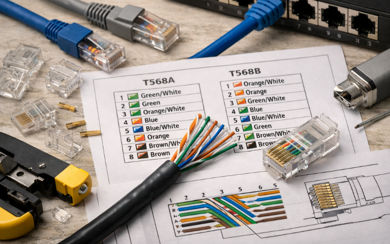
Two main wiring standards are used worldwide: T568A and T568B. Both follow the same electrical design but use a different color order for two of the wire pairs.
The difference between them is mainly the position of the green and orange pairs. Functionally, both standards work the same, and network speed or quality does not change as long as both ends of the cable use the same standard.
T568B has become the most common choice for modern installations because it has historically been used in commercial networking. Many ready-made cables follow this layout, so using it keeps installations consistent.
T568A is still used in some government buildings, residential wiring, or structured cabling systems where it was specified earlier. The key point is consistency. Mixing the standards on one cable creates a crossover connection rather than a normal patch cable.
Straight-Through vs. Crossover Ethernet Wiring
A straight-through cable uses the same wiring standard on both ends. This is the most common cable type and is used to connect devices such as a computer to a router, or a switch to a modem.
A crossover cable uses T568A on one end and T568B on the other. This swaps the transmit and receive pairs so two similar devices can communicate directly, such as two computers or two switches without a network device between them.
Modern hardware often supports Auto-MDIX, which automatically detects the cable type and adjusts the signal internally. Because of this, crossover cables are rarely required today. Still, they may be useful when working with older equipment or troubleshooting legacy networks.
How to Read an RJ45 Wiring Diagram Correctly
Reading an RJ45 wiring diagram correctly starts with understanding connector orientation. When holding the plug with the metal contacts facing you and the clip pointing away, pin one is always on the left side.
Identifying pin one correctly is important because reversing the connector can mirror the wiring order. This is one of the most common mistakes beginners make when building cables.
A good habit is to double-check the wire colors against the diagram before crimping. If even one wire is in the wrong slot, the cable may still connect but operate at reduced speed or fail under load. Taking a few extra seconds to confirm the order helps avoid hours of troubleshooting later.
Tools and Materials Needed for RJ45 Wiring
Building Ethernet cables requires only a few basic tools, but using the right ones makes a big difference. Ethernet cable itself is available in several categories, such as Cat5e, Cat6, or Cat6A, each supporting different speeds and distances.
RJ45 connectors must match the cable type, especially when working with thicker cables that need connectors designed for larger conductors. A crimping tool secures the connector to the cable, while a cable tester checks whether the wires are connected correctly after crimping.
When wiring wall outlets, a punch-down tool is often used instead of a crimper. This tool presses wires into a keystone jack where they lock into place. Using the correct tool ensures strong connections and reduces the chance of signal loss.
Common Wiring Mistakes That Cause Network Problems
Small wiring errors can lead to slow speeds, unstable connections, or complete signal failure. One frequent mistake is untwisting the wire pairs too far before inserting them into the connector. This increases interference and weakens the signal.
Another common issue is using different wiring standards on each end of a cable without realizing it. This creates a crossover cable when a straight-through connection was intended.
Poor crimping can also cause problems if the wires do not reach the end of the connector or the outer jacket is not secured under the crimp tab. Finally, mixing cable categories, such as joining a high-speed cable with older connectors, can limit performance even if the wiring order is correct.
When to Use an RJ45 Diagram for Wall Jacks vs. Patch Cables
RJ45 wiring diagrams are used for both patch cables and wall jacks, but the installation method differs slightly. Patch cables use connectors that are crimped onto the cable, while wall jacks use punch-down terminals that hold wires in place.
Because punch-down terminals arrange wires in slots rather than a straight line, diagrams for wall jacks may look slightly different. However, the color order and pair placement follow the same standards.
Choosing the right method depends on the installation. Patch cables are ideal for short connections between devices, while wall jacks provide a clean, permanent solution for structured cabling inside homes or offices. In both cases, following the correct RJ45 wiring diagram ensures a reliable network connection.
Conclusion
An accurate RJ45 wiring diagram is one of the most useful tools when working with Ethernet cables. It ensures wires are placed in the correct order, helps maintain signal quality, and prevents many common connection problems.
Whether you are wiring a wall outlet, repairing a damaged cable, or building custom network leads, following the proper diagram saves time and avoids frustration. By using the correct standard, keeping wire pairs intact, and checking your work carefully, you can create cables that deliver stable and high-speed network performance for years to come.
FAQs
1. What is the difference between an RJ45 wiring diagram and a pinout diagram?
An RJ45 wiring diagram shows both the wire colors and their positions in the connector, while a pinout diagram focuses mainly on the numbered electrical connections.
2. Which RJ45 wiring standard should I use for home networks?
Most home networks use T568B because it matches the wiring of most pre-made cables, but either standard works if both ends are the same.
3. Can a wrongly wired RJ45 cable still work?
Yes, sometimes it may connect at lower speeds, but performance will be unstable and errors can occur, so correct wiring is always recommended.
4. Do modern devices still need crossover cables?
Usually not, since most devices support Auto-MDIX, but crossover wiring can still be useful for older equipment or special network setups.